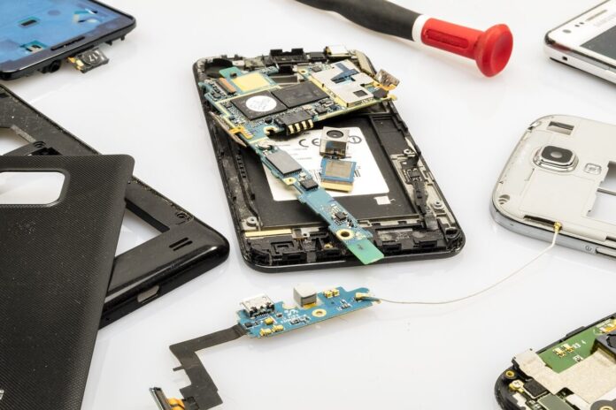
Mobile Phone Repair Version 2
We published the first version of the General Concepts to Know for Mobile Phone Repair. This topic is a continuation of the previous topic.
General Concepts to Know for Mobile Phone Repair.
Types of Electric Current
Types of electric current are used as terms. Just as current (ampere) has direct and alternating types, the voltage also (volts) has direct and alternating volts.
Direct current
Current flowing in the same direction and at the same intensity over time is called direct current. Direct current is presented with “DC” or ⎓ symbols.

Direct current can be either positive or negative. In direct current, there are the concepts of “positive” and “negative”. In our world, the color red is always positive (+). and the color black is always negative (-).
Sources of direct current;
Batteries, Accumulators, and batteries (batteries are included in this group), DC power supplies, chargers.
Alternating current
The current that changes its direction and intensity depending on time is called alternating current.
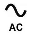
Alternating current is denoted by “AC”. its symbol is “~”
The city grid is alternating current. In alternating current, there are the concepts of “phase” and “neutral”.
Electrical circuit
The purpose of the education of this topic is to give the technician a perspective.
Open circuit
In this circuit, which occurs when the switch is open, the light bulb used as a load does not light, since the current circuit is not completed.
We can think of the open circuit on the phone as the following; broken element, coil, resistor, etc. as open-circuited elements and mechanically non-contact connection points.
Closed-circuit
When the switch is closed, the current runs the load by completing its circuit over the load. So the bulb lights and that means there is a transmission on the mechanic connection paths. The meaning of closed circuits in mobile phone repair is; the path is intact or the elements on the path are in place and intact.
Short circuit
Electric current always travels in the shortest path. The short circuit is undesirable. In this case, the circuit draws theoretically infinite current. It lowers the voltage level at the source. A short circuit is both the cause and the fault itself. A short-circuited element causes the preceding circuit element to deteriorate as well. An electronic device repair technician, while examining the problem in front of him, must determine whether the device in front of him has an open circuit, closed circuit, or short circuit conditions. When this distinction is not made, it is a waste of time and material in the first place. If the short circuit condition is detected late, the device in your hand may become unusable. So the motherboard might get completely broken.
The term ”Serial”
Serial Connection

You can think of the concept of serial as a cascade of locomotives. In an electrical circuit, connected elements are in order of; “positive”, “negative”, “positive”, “negative” and it goes on like this.
On serial lines, there are two reasons for errors to occur
*path breaks
*failures caused by circuit elements;
a – Cold soldering of feet
b- broken feet
c- dislocation coma
d- short circuit
The term “Parallel”
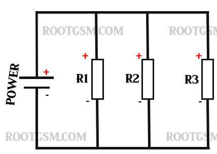
Parallel connection in the electrical circuit; “positive” ends are connected only with “positive” ends, and “negative” ends are connected only with “negative” ends.

in parallel arms; In the case of a short circuit of circuit elements, all circuit elements connected to the same line fall into a short circuit.
Open Schema
It is the clearest drawn version of the circuit. open schema; It shows the connection between the layers, the technical value of the element on the diagram, and the connection between the elements. It allows us to understand the purpose and duties of the elements on the circuit.
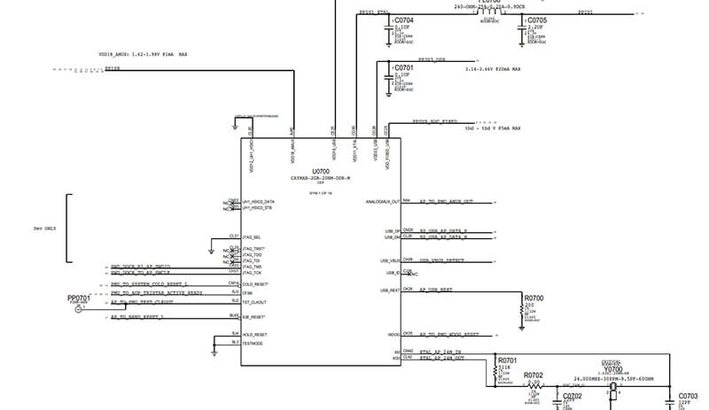
With the open schema, the working principle of the circuit, the operation of the circuit, and the operation between the layers are clearly understood. We get an idea of where to start fixing the error and the weakest places in the circuit. With the open schema, we see the address information on the layout of each element. With the open schema, we learn the answer to our questions such as which elements we will solder to, which components we will change. When searching for faults; We elaborate on open schemas.
Layout Plan
It is exactly the same as the layout on the circuit board. In the open schema, they are the drawings that allow the (addressed) elements to be easily found on the circuit boards, numbered such as u202, c210. The address/location information in the open schema and the address/location information in the layout plan is exactly the same. The layout plan allows the location information of the numbered elements to be located exactly on the plan in the open schema. Thanks to the layout plan, the lack of elements and faults etc. on the motherboard are detected.
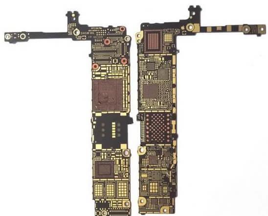
Absolutely no comments can be made on the layout plan. With the layout plan, only the location of the element on the motherboard is detected.
Circuit board (motherboard)
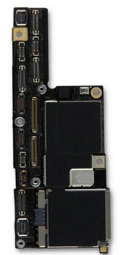
The plate that holds the electronic circuit elements together and provides the electrical connection between these components is called a PCB (printed circuit board). All electronic circuits such as television, mobile phone, tablet, PC, etc. produced are mounted on a PCB. There are different types of printed circuits according to the characteristics and size of the electronic circuit. Simple circuits can fit in a single layer. Printed circuits produced for high-tech devices such as mobile phones, laptops, etc. are produced in multiple layers.
We shared what you need to know for mobile Phone Repair in general. It cannot be shared without indicating the source.

