Table of Contents
The Micro USB cable is a standard accessory connecting various devices, such as smartphones, tablets, and cameras, to a power source or computer. The functionality of the Micro USB cable is made possible by the arrangement of pins within the connector. By comprehending the functions of these pins, a technician can gain insight into how the cable operates and how to utilize it for different purposes.
Main Points
- The purpose of each pin in a Micro USB cable
- How the arrangement of pins allows for data transfer and charging
- The significance of the pin layout for device compatibility
- Common issues related to pin malfunction in Micro USB cables
Anatomy of the Micro USB Connector: Pin Function Overview
The micro USB connector is a small and versatile port commonly used for charging and data transfer in various electronic devices. Understanding the different pin functions of the micro USB connector is crucial for proper usage and troubleshooting. Here is an overview of the pin functions:
Main Pin Functions:
- VCC (Voltage Common Collector): This pin provides power to the connected device.
- D- and D+ (Data Pins): These pins facilitate data transfer between the device and the host.
- GND (Ground Pin): This pin serves as the electrical ground for the connector.
Understanding the anatomy of the micro USB connector and its pin functions is essential for anyone working with electronic devices. It allows for proper connections, troubleshooting, and maintenance of devices using this widespread connector.
Pin Configuration of Micro USB Cables
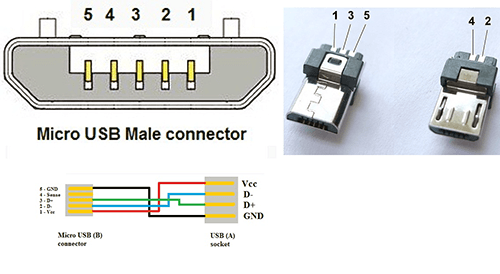
The pin configuration is essential for proper functionality when it comes to micro USB cables. These cables feature five pins, each serving a specific purpose. The VCC (Voltage Common Collector) pin provides the power supply. In contrast, the D- (Data Minus) and D+ (Data Plus) pins are responsible for data transfer. The GND (Ground) pin provides proper grounding, and the ID (Identification) pin helps detect the device. By familiarizing yourself with the pin configuration, you can troubleshoot connectivity issues and ensure optimal performance.
Micro USB Pin Configuration
| Pin | Function |
|---|---|
| VCC | Power Supply |
| D- | Data Minus |
| D+ | Data Plus |
| GND | Ground |
| ID | Device Detection |
By understanding the functions of each pin in a micro USB cable, users can ensure proper connectivity and troubleshoot any issues that may arise. Knowing the pin configuration is crucial for a seamless experience, whether charging a device or transferring data.

The Role of Each Pin in a Micro USB Cable for Data Transfer
Regarding the functionality of a micro USB cable for data transfer, each pin is crucial in ensuring a smooth and efficient process. The four pins – VCC, D-, D+, and GND – are responsible for carrying power, data signals, and grounding. VCC delivers the necessary power for the device, while D- and D+ pins handle data transmission. Lastly, the GND pin ensures a secure grounding connection, ensuring the stability of the data transfer process.
Power Delivery in Micro USB Cables: Understanding Pin Functions
When it comes to micro USB cables, understanding the pin functions is crucial for efficient power delivery. The pins are the small metal connectors at the end of the cable that transmit power and data. There are five pins in a micro USB cable, each serving a specific function:
- VBUS (Voltage Bus)
VBUS pin is responsible for carrying the electrical power from the charger to the device.
- GND (Ground)
The GND pin serves as the electrical circuit’s reference point and completes the current’s electrical path.
- D+ and D- (Data Transmission)
The D+ and D- pins transmit data between the device and the charger.
- ID (Identification)
The ID pin helps identify the type of device connected through the cable.
- OTG (On-The-Go)
OTG pin enables mobile devices to act as a host for peripherals like USB drives and keyboards.
Understanding the role of each pin in a micro USB cable is essential for ensuring proper power delivery and data transmission.
Deciphering the Micro USB Pinout: A Guide for Electronics Professionals
Mastering the micro USB pinout is not just a skill, it’s a necessity for electronics professionals dealing with mobile devices and other small gadgets. As technology advances at a rapid pace, it’s crucial to keep pace with the intricacies of these miniature connectors. In this comprehensive guide, we will navigate the complex world of micro USB pinouts, offering invaluable insights and practical tips for deciphering their wiring configurations. Whether you’re a seasoned pro or a beginner, this guide will deepen your understanding of micro USB pinouts and empower you to work with them more efficiently.
Synchronizing and Charging: How Micro USB Pins Facilitate Device Communication
The micro USB pin configuration plays a crucial role in enabling the synchronization and charging of electronic devices. The micro USB connector with five pins facilitates data transfer and power between devices.
Pin 1 and Pin 5 in the micro USB connector enable device synchronization, allowing for the seamless transfer of data between devices. Meanwhile, Pin 2 and Pin 3 facilitate device charging, providing the necessary power for device operation.
When these pins are united, they form a communication superhighway, a power conduit, and a synchronization bridge between devices, guaranteeing flawless functionality.
“The micro USB pins are the unsung heroes of device connectivity, enabling the seamless transfer of data and power.”
Pin Configuration of Micro USB Connector
| Pin No. | Function |
|---|---|
| 1 | Data + |
| 2 | Data – |
| 3 | VCC (+5V) |
| 4 | ID |
| 5 | GND |
The Electrical Characteristics of Micro USB Pins: A Technical Examination
When it comes to the electrical characteristics of micro USB pins, it is crucial to understand the technical aspects in detail. The following examination delves into the intricate features of micro USB pins:
- Pin Configuration
The micro USB connector has five pins, each serving a specific function. These pins include Vbus, D-, D+, ID, and GND.
- Voltage and Current Ratings
Micro USB pins’ voltage and current ratings are critical for safe and efficient power transfer. The standard voltage rating is 5V, while the current rating ranges from 500mA to 1.8A.
- Data Transfer Speed
The D—and D+ pins play a crucial role in data transfer. These pins transmit data at different speeds, with USB 2.0 supporting a maximum transfer rate of 480 Mbps and USB 3.0 supporting up to 5 Gbps.
Another article – SM-A032F A03 Core Testpoint


